tinkerCAD案例:25. 量角器 - 测量角度
tinkerCAD案例:25. 量角器 - 测量角度
原文
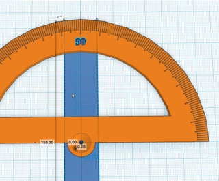
Now we’re going to make a protractor! A Protractor is one of the most basic, but essential, tools for making measurements. It is, then, surprising that the modern protractor is barely over 200 years old.
现在我们要做一个量角器!量角器是用于进行测量的最基本但必不可少的工具之一。令人惊讶的是,现代量角器只有 200 多年的历史。
A protractor measures angles from a point, along two radiuses, one aligned with the bottom, and the next aligned with a mark made along the circumference of the protractor.
量角器从一个点开始,沿着两个半径测量角度,一个与底部对齐,下一个与沿量角器圆周的标记对齐。
Today, we’re going to explore the protractor, and through building it, gain a deeper understanding about using it.
今天,我们将探索量角器,并通过构建它,更深入地了解使用它。
step 1: 标尺助手
We will be making extensive use of the Ruler Helper, perhaps in ways you have not done before. Therefore, it is important that we begin with it in the right place.
我们将广泛使用标尺助手,也许以您以前从未做过的方式。因此,重要的是我们在正确的地方开始。
It is common with most tools, on a computer or in the real world, to set up the work environment, first, so everything you’ll need will be at your disposal.无论是在电脑上还是在现实世界中,使用大多数工具时,通常都要先设置好工作环境,这样你所需要的一切都能随手可得。
说明
-
Drag the Ruler Helper so that its Origin is at the center of the Workplane. Make sure to align the axes of the ruler tool to a major (thicker) grid line. Grid lines are 1mm apart and major grid lines happen every 10mm. Aligning this ruler helper to the major grid lines helps you make movement decisions faster.
拖动标尺助手,使其原点位于工作平面的中心。确保标尺工具的轴与主要(较粗)网格线对齐。网格线相距 1 毫米,主要网格线每 10 毫米出现一次。将此标尺帮助器与主要网格线对齐可帮助您更快地做出移动决策。
-
Today, we’ll be using the Ruler Helper in “Use midpoint” mode. We will not be able to set the mode until we have placed an object on the workplane. Drag out our first piece, a cylinder. We don’t need to worry about being precise in placement, the ruler helper will allow us to have fine grained control over the placement of objects.
今天,我们将在 "使用中点 "模式下使用标尺助手。拖出我们的第一个对象,一个圆柱体。我们不必担心摆放位置的精确性,标尺助手可以让我们对物体的摆放位置进行精细控制。
-
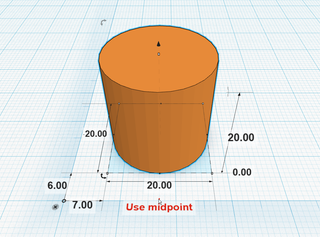
Select our new cylinder. You’ll notice a small triangle or arrow below the object, centered on its X axis. If you hover over the triangle, you’ll see the text ‘Use midpoint’ appear. If you click this, it will change the mode. The text will then change to ‘Use corner’ which will let you know you are in midpoint mode.
选择我们的新气缸。您会注意到对象下方有一个圆内三条线的图标,以 X 轴为中心。如果将鼠标悬停在图标上,则会看到“使用中点”文本。如果单击此按钮,它将更改模式。然后,文本将更改为“使用端点”,这将处于中点模式。
-
You’ll now notice that the Ruler Helper measures from the origin to the center of the object. If you click on the measurements along the X and Y axes and set them to Zero, your object will move to be perfectly centered on the origin. Since we are designing a protractor, this will be the point from which all measurements, while using the protractor, will radiate.
现在,您会注意到标尺助手从对象的原点到中心进行测量。如果沿 X 轴和 Y 轴单击测量值并将其设置为零,则对象将移动到原点上完全居中。由于我们正在设计量角器,因此在使用量角器时,这将是所有测量值的辐射点。
step 2:创建弧线
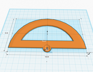
- The basic form of a protractor is an arc with demarcations along its edge. In this step, we’ll make that arc.
量角器的基本形式是沿其边缘有刻度线的弧形。在此步骤中,我们将创建该弧线。
说明
-
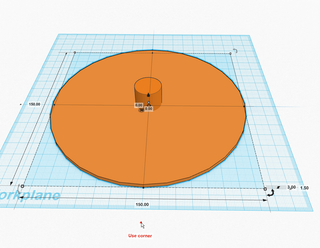
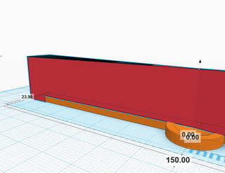
Resize your existing cylinder to be 150mm in diameter and 3mm along the Z axis. Then, make sure its center is 1.5mm above the workplane (1.5mm on the Z axis.) Remember, we are in midpoint mode, so the distance measure along the Z axis will be to the middle of the object, not the bottom.
将现有圆柱体的大小调整为 150 毫米直径和沿 Z 轴 3 毫米。然后,确保其中心在工作平面上方 1.5 毫米(Z 轴上为 1.5 毫米)。请记住,我们处于中点模式,因此沿 Z 轴的距离测量将位于物体的中间,而不是底部。
-
Drag another cylinder to the center of the other. You can’t see the grid lines, so just eyeball it, and then correct the position using the Ruler Helper.
将另一个圆柱体拖动到上一个圆柱体的中心。你看不到网格线,所以只需目视它,然后使用标尺助手校正位置。
-
Continue to the next step.
继续执行下一步。
step 3:制作斜边
-
We’ll want the edge of our protractor to be thin while keeping the rest of the protractor ridged. So what we’ll do is keep the body 3mm but taper the edge almost to a point. This type of feature is referred to as a beveled edge.
我们希望量角器的边缘很薄,同时保持量角器的其余部分有脊。因此,我们要做的是保持机身3毫米,但将边缘几乎逐渐变细。这种类型的特征称为斜边。Think of a bevel as cutting an sharp edge off to make two edges which are half as sharp.
将斜面视为切掉锋利的边缘,使两个边缘的锋利程度减半。
说明
-
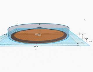
Set the second cylinder to be 160mm in diameter and 20mm tall, then move its center to 11mm above the Workplane.
将第二个圆柱体的直径设置为 160 毫米,高 20 毫米,然后将其中心移动到工作平面上方 11 毫米处。
-
For the next few steps, I have set the cylinder to a hole just so we can see through it.
在接下来的几个步骤中,我将圆柱体设置为一个空心,以便我们可以透过它看到它。
-
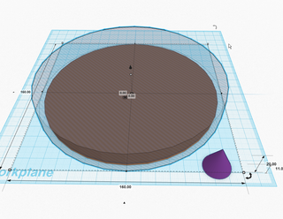
Drag out a cone, but keep it outside of the cylinder so the cylinder won’t be in the way when we resize the cone.
拖出一个圆锥体,但将其放在圆柱体外部,这样当我们调整圆锥体大小时,圆柱体就不会碍事。
-
Continue to the next step.
继续执行下一步。
step 4. 制作斜边
从上一步继续
说明
-
Make the cone 150mm in diameter and 20mm tall. Move its center to 11mm off of the Workplane and center the cone to the origin.
使圆锥直径150mm,高20mm。将其中心移动到离工作平面 11 毫米的位置,并将圆锥体居中到原点。
-
Turn the cone in to a hole, and turn the cylinder in to a solid (color).
将圆锥体转入孔,然后将圆柱体转入实心(颜色)。
-
What we are now going to do is remove the cone from the larger cylinder. Select all the objects, then unselect the bottom cylinder, and press group.
我们现在要做的是从较大的圆柱体上取下锥体。选择所有对象,然后取消选择底部圆柱体,然后按组。
-
Turn this object in to a hole. You should now have a hole in the shape of a negative of a cone.
把这个物体变成一个洞。您现在应该有一个圆锥体负片形状的孔。
-
Group this shape and our first cylinder. This will make a bevel on our protractor.
将此形状和我们的第一个圆柱体分组。这将在我们的量角器上制作一个斜面。
-
Continue to the next step.
继续执行下一步。
step 5. 将量角器切成两半
Now we’re going to cut the protractor in half to create the straight edge.
现在我们要把量角器切成两半,以创建直线边缘。
说明
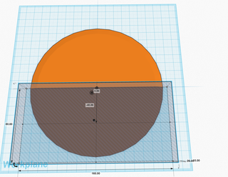
- Drag a box to the workplace and make it larger than half off the cylinder. I made mine 160mm by 80mm.
将一个盒子拖到工作场所,使其大于圆柱体的一半。我做了 160 x 80 毫米。
- We will then center it on the X axis, but we will align the edge to the Y axis. To do this, take the box’s Y dimension and divide it in half. Use this number to move the box below the Y axis by making this value negative. In my case, the center of the box will be at -40mm on the Y axis.
然后,我们将它在 X 轴上居中,边缘与x 轴对齐。为此,请取盒子的 Y 尺寸并将其分成两半。使用此数字通过将此值设置为负数来将框移动到 Y 轴下方。在我的情况下,盒子的中心将在 Y 轴上的 -40mm 处。
然后,我们将以 Y 轴为中心,但将边缘对准 X 轴。为此,将方框的 Y 轴尺寸对半。将该数值设为负数,从而将方框移动到 Y 轴下方。在我的例子中,方框的中心将位于 Y 轴上的-40 毫米处。
------
- Make this object a hole and then group it with the cylinder.
将此对象设置为孔,然后将其与圆柱体分组。
step 6. 制作量角器中心点
The focal point of a protractor is where the two lines, which define an angle, meet. We need to make a space for the point to be visible so we are able to view the point from which the two lines radiate.
量角器的焦点是定义角度的两条线相交的地方。我们需要为该点创建一个可见的空间,以便我们能够查看两条线辐射的点。
说明
-
Create a cylinder that is 16mm in diameter and 3mm tall. Center it on the origin, and move the center of the cylinder 1.5mm above the workplane.
创建一个直径为 16 毫米、高 3 毫米的圆柱体。将其居中放在原点上,然后将圆柱体的中心移动到工作平面上方 1.5mm。
-
Group this object with the semi-circle.
将此对象与半圆分组。
-
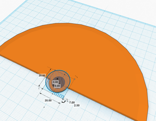
Drag out a cone to the center of the ruler and rotate it 180° around the Y axis so that the point of the cone points in the negative direction along the Z axis.
将圆锥体拖到标尺的中心,并绕 Y 轴旋转 180°,使圆锥体的点沿 Z 轴指向负方向。
-
Make the cone 7mm tall and move it so it’s center is 2.5mm above the workplane.
使圆锥体高 7 毫米并移动它,使其中心在工作平面上方 2.5 毫米。
-
Turn the cone in to a hole and group everything.
将锥体转变为空心并对所有东西进行分组。
-
Continue to the next step.
继续执行下一步。
step 7. 制作观察口
We’ll need a viewing window through which we read the lines when we are measuring.
我们需要一个观察窗口,当我们测量时,我们通过它读取线条。
We have an opportunity, now, to customize your protractor. For instance, how thick do we want the straightedge rule and the protractor rule to be? I chose 15mm and 20mm, respectively, but you may make these features smaller, leaving more room for the window. I’ll show you how I came to my measurements so, if you like, you can calculate your own.
现在,我们有机会定制您的量角器。例如,我们希望直线刻度尺和量角器刻度尺有多粗?我分别选择了 15mm 和 20mm,但您可以使这些功能更小,为窗口留出更多空间。我将向您展示我是如何进行测量的,因此,如果您愿意,您可以自己计算。
说明
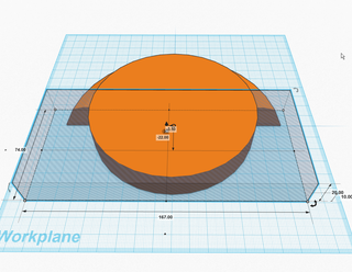
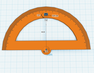
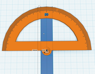
- Drag out a new cylinder and center it to the origin along the X and Y axes. My protractor is 150mm in diameter, so to make a 20mm wide rule, I need to subtract 20mm from 150mm, twice (150-40=110mm). I made my cylinder 110mm in diameter.
拖出一个新圆柱体,并沿 X 轴和 Y 轴将其居中到原点。我的量角器的直径为150mm,因此要制定20mm宽的刻度尺,我需要从150mm中减去20mm,两次(150-40 = 110mm)。我把我的圆柱体的直径做了110毫米。
- Drag out a new box and center it to the origin along the X axis. Make it larger than half of the new cylinder. The critical dimension is the Y axes. I made my box’s Y axis dimension 74mm.
拖出一个新框,并沿 X 轴将其居中到原点。使其大于新圆柱体的一半。关键尺寸是 Y 轴。我使盒子的Y轴尺寸为74mm。
- To make a 15mm wide straightedge rule, divide the Y axis dimension of the box in half (74/2=37mm) and then subtract our desired dimension from this (37-15=22m). Move the center of this box to -22mm on the Y axis.
要制作 15mm 宽的下边刻度尺,请将盒子的 Y 轴尺寸分成两半 (74/2=37mm),然后从中减去我们想要的尺寸 (37-15=22mm)。将此框的中心移动到 Y 轴上的 -22mm。
- Continue to the next step.
继续执行下一步。
step 8. 组合量角器中心点
说明
1. Make the box a hole and group the new cylinder and the box together.
将盒子转变为空心,并将新圆柱体和盒子组合在一起。
------
2. Turn this new shape in to a hole and group it with the rest of the protractor.
将此新形状转变为空心,并将其与量角器的其余部分分组。
------
3. Continue to the next step.
继续执行下一步。
step 9. 制作刻度线
We now have a pristine protractor shape, but it isn’t very useful without degree demarcations. For ease of reading, we will make three styles of demarcation, one length for intervals of ten, a shorter length for measures ending in five, and the shortest length for all other measures.
我们现在有一个原始的量角器形状,但如果没有度数分界线,它就不是很有用。为了便于阅读,我们将制作三种分界方式,一种长度用于以 10° 为间隔,较短的长度用于以 5 °的度量,最短长度用1°度量。
I am making my demarcations 10mm long, 8mm long, and 7mm long, respectively. If you’d like to customize yours, refer back to step 8!
我分别将分界线定为 10 毫米长、8 毫米长和 7 毫米长。如果您想自定义,请参阅步骤 7!
说明
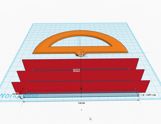
- Drag out a box and make it 150mm along the X axis and 0.5mm along the Y axis.
拖出一个框,使其沿 X 轴 150 毫米,沿 Y 轴使其 0.5 毫米。
- Drag out another box and make it 130mm along the X axis. Make it 3mm tall (along the Z axis) and move its center so it is 1.5mm off of the workplane. Turn it in to a hole.
拖出另一个盒子,沿X轴使其为130mm。使其高 3 毫米(沿 Z 轴),并移动其中心,使其离工作平面 1.5 毫米。把它变成空心。
- Use the Align tool to center these objects to each other on the X and Y axes, and so they share lower Z limits.
使用对齐工具将这些对象在 X 轴和 Y 轴上彼此居中,以便它们共享较低的 Z 限制。
- Duplicate these shapes twice more so you have three sets total.
再复制这些形状两次,这样总共有三组。
- We will leave one of these pairs of objects alone, and we’ll use that for the degree intervals of 10.
我们将保留其中一对对象,我们将将其用于 10 °间隔。
- Then, we will change one of the copies, for the intervals ending in 5, so that the hole is 134mm long.
然后,我们将更改其中一个副本,间隔以 5 结尾,使孔长 134 毫米。
- The last, for all other intervals, set the hole to be 136mm long.
最后一个,对于1°间隔,将孔设置为 136 毫米长。
- Then, group these pairs of objects. Do not group them all together, just each hole with its corresponding box so we have three separate objects.
然后,对这些对象对进行分组。不要将它们全部组合在一起,只需将每个孔及其相应的框组合在一起,因此我们有三个单独的对象。
- Continue to the next step.
继续执行下一步。
step 10. 制作10°刻度盘
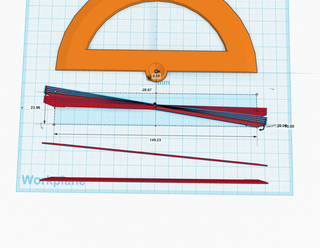
Now we will rotate these new objects so that we can assemble them to define a single interval of demarcations from 1 to 10.
现在我们将旋转这些新对象,以便我们可以组装它们以定义从 1 到 10 的单个分界区间。
说明
-
Leave the object for measures at intervals of 10 degrees alone.
将最初对象留作单独测量的间隔为 10 度。 -
Take the object we made for the measures ending in 5 and rotate that shape about the Z axis in the positive (clockwise) direction by 5°.
以我们为以 5 结尾的测量值制作的对象,将该形状沿正(顺时针)方向绕 Z 轴旋转 5°。
- Take the object we made for all other measures and rotate it 1°, then duplicate it, then rotate the duplicate one degree, then duplicate it two more times.
拿我们为1°测量值制作的对象,将其旋转 1°,然后复制它,然后将复制品旋转一度,然后再复制两次。
- Duplicate these 4 objects and rotate them 5°. There should be a gap after the fourth mark.
复制这 4 个对象并将它们旋转 5°。第四个标记之后应该有一个间隙。
- Select all of these objects and align them to each other so that they all share the same center.
选择所有这些刻度线对象并将它们彼此对齐,以便它们都共享同一中心。
- Continue to the next step.
继续执行下一步。
step 11. 检查10°刻度盘
Now that we have one sequence of demarcations, it is easy to replicate them for every 10 degrees.
现在我们有一个分界序列,很容易每 10 度复制它们。
说明
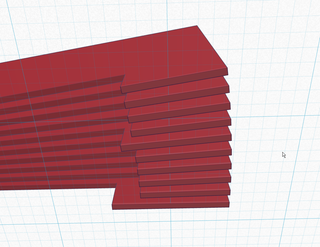
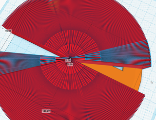
- Look at this new group of objects from below the workplane. You should see something like what is above. Eight short marks, one medium mark, and one long mark.
从工作平面下方查看这组新对象。您应该看到类似上面的内容。8 个短标记、1 个中标记和一个长标记。
- Group these objects. 对这些对象进行分组。
- Continue to the next step.
继续执行下一步。
step 12. 放置第一组刻度线
We’re going to place and inspect the first group of demarcations.
我们将放置并检查第一组分界线。
说明
- Move this group so that its center is located at the origin, and above the workplane 11mm (11mm positive on the Z axis.)
移动此组,使其中心位于原点,工作平面上方 11mm(Z 轴上正 11mm)。
- If you look at the straight edge of the protractor, you should see that the longest of the demarcations is half on and half off the edge. This is EXACTLY where we want the mark.
如果你看一下量角器的直边,你应该看到最长的分界线一半在边缘上,一半在边缘上。这正是我们想要标记的地方。
- Continue to the next step.
继续执行下一步。
step 13. 制作完整刻度盘
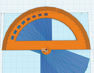
We are going to duplicate and rotate the demarcations until we make a complete circle.
我们将复制和旋转分界线,直到我们形成一个完整的圆。
说明
-
Select the first group of demarcations and duplicate them.
选择第一组分界线并复制它们。 -
Rotate the duplicate demarcations by 10°.
将重复的分界线旋转 10°。
- Repeat this process until you have completed the arc.
重复此过程,直到完成弧形。
- Group all of the shapes which represent the demarcations and put this group in to hole mode.
将所有表示分界线的形状分组,并将该组置于孔模式。
- Finally, combine this group of shapes and the blank protractor in to one shape.
最后,将这组形状和空白量角器组合成一个形状。
- YOU WILL NOTICE that we have 180° of demarcations that will be cutting in to nothing.Why is this? Tinkercad allows us to rotate objects around their center. The challenge is, sometimes we want to rotate an object around a different point. So what we have done is extended the size of the object so that the point we wish to rotate the object around IS the center of the object.This will become more clear when we place our lettering.
您会注意到,我们有 180° 的分界线,这些分界线将被切割成空。Tinkercad 允许我们围绕中心旋转对象。难点在于,有时我们希望围绕不同的点旋转对象。因此,我们要做的就是扩展对象的大小,使我们希望围绕对象旋转的点成为对象的中心。
- Continue to the next step.
继续执行下一步。
step 14 检查刻度盘
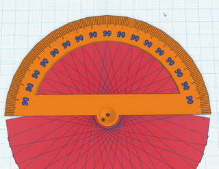
Lets take a moment to check if our demarcations are right.
让我们花点时间检查一下我们的划分是否正确。
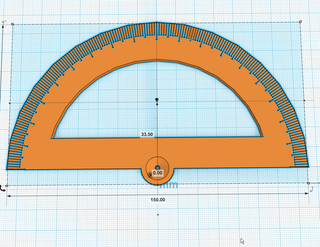
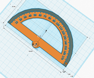
If you notice, the protractor is already doing its job. The focal point is on the origin, the straight edge is in line with the X axis, the measures for 0° and 180° are along the X axis. The measure for 90° is along the Y axis.
如果您注意到,量角器已经在做它的工作了。焦点在原点上,直边与 X 轴对齐,0° 和 180° 的测量值沿 X 轴。90° 的测量值沿 Y 轴。
If this is true for your protractor, good job!
如果您的量角器是真的,那就干得好!
说明
- Continue to the next step.
继续执行下一步。
step 15. 添加数字文本
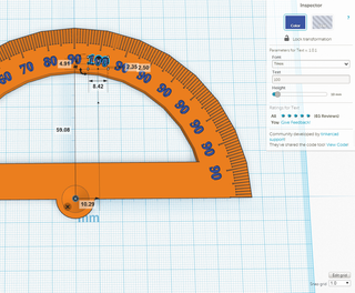
We are going to label this protractors increments of 10, starting with the 90 degree demarcation up at the top.
我们将标记这个量角器增量为 10,从顶部的 90 度分界线开始。
Placing the text, formatting the text, and scaling the text are all arbitrary. What is key is that the text fits, is large enough to print, but is not so large that the text will crowd the neighboring text.
置入文本、设置文本格式和缩放文本都是任意的。关键是文本适合,足够大,可以打印,但不要太大以至于文本会挤占相邻的文本。
说明
- Use the Text shape generator to create the first label, at the center most demarcation, and enter the text “90”.
使用文本形状生成器在最中心的分界处创建第一个标签,然后输入文本“90”。
- Decide now if you want raised text, recessed text, or text that goes all the way through.
现在决定是要凸起的文本、凹陷的文本还是一直贯穿的文本。
-
If you want the text to cut all the way through your protractor, you will need to choose a stencil font, which 4. means a font that has bridges to hold the centers of lettering to the rest of the part. In the Text tool, Majorsnafu is the only stencil font in Tinkercad.
如果您希望文本一直剪切到量角器中,则需要选择模板字体,即 4。表示具有桥接以将字母中心固定到零件其余部分的字体。在文本工具中,Majorsnafu是Tinkercad中唯一的模板字体。
如果您想让文字一直穿过量角器,则需要选择模版字体,即4。 一种具有桥接功能的字体,以将字母中心与部件的其余部分连接起来。在文本工具中,Majorsnafu 是 Tinkercad 中唯一的模版字体。
------ -
Position your font, along the Z axis, how you want it. I want recessed text, so I put the bottom of the text 1mm below the top surface of the protractor.
沿 Z 轴放置字体,按所需方式放置。我想要凹陷的文本,所以我将文本的底部放在量角器顶部表面下方 1 毫米处。
- Continue to the next step.
继续执行下一步。
step16. 制作数字旋转轴
Now we need to rotate the text along the arc. This would be painstaking, but we just learned a trick to make this easy. Again, we are going to make sure that the text rotates, easily, around the origin.
现在我们需要沿弧线旋转文本。这将是艰苦的,但我们刚刚学会了一个技巧来简化它。同样,我们将确保文本轻松地围绕原点旋转。
说明
- Drag a block to the origin of the Ruler Helper
将长方体拖动到标尺助手的原点
- Resize it to so that it’s length along the Y axis is 150mm.
调整其大小,使其沿 Y 轴的长度为 150 毫米。
- Position the block so that it is completely beneath the workplane (the top of the block is at a negative Y Value.)
放置块,使其完全位于工作平面下方(块的顶部为负 Y 值)。
- Make sure the object is centered (that the center of the object has an X and Y positional value of 0.)
确保对象居中(对象的中心的 X 和 Y 位置值为 0。
- This new object is our Rotational Helper
这个新对象是我们的旋转助手
- Group your lettering and your Rotational Helper together.
将您的字母和轮换助手组合在一起。
- Continue to the next step.
继续执行下一步。
step 17. 旋转完成其它数字
Like with the demarcations, we are going to rotate the lettering around the origin, but unlike the demarcations, the lettering is completely outside of the origin. Therefore, to make the rotation easy, we added the lettering to a group which DOES have a center which coincides with the origin, at least on the X and Y axis.
与分界线一样,我们将围绕原点旋转字母,但与分界线不同的是,字母完全在原点之外。因此,为了使旋转变得容易,我们将字母添加到一个组中,该组确实有一个与原点重合的中心,至少在 X 和 Y 轴上。
说明
- Duplicate the group with the lettering
Duplicate字母组
-
Rotate the lettering 10° 将字体旋转 10°
------ -
Repeat in both directions in 10° increments
以 10° 为增量在两个方向上重复
- Continue to the next step.
继续执行下一步。
step 18. 删除数字旋转轴
Our Rotational Helper has done its job. It is now time to remove it.
我们的轮换助手已经完成了它的工作。现在是时候删除它了。
说明
- Ungroup the lettering groups.
取消字母组的分组。
- Delete all of the Rotational Helpers.
删除所有轮换助手。
- Continue to the next step.
继续执行下一步。
step 19. 编辑刻度值
Now, we just need to edit the lettering to match the angular measure.
现在,我们只需要编辑字母以匹配角度测量值。
说明
- Change the lettering to match your desired numbering scheme.
更改字母以匹配所需的编号方案。
- If you want to make stencils or recessed text, turn the text objects in to holes.
如果要制作模具或凹陷文本,请将文本对象转换为孔。
- Group the lettering and the protractor.
对字母和量角器进行分组。
- Continue to the next step.
继续执行下一步。
step 20. 打印
-
This object, which is nearly completely flat, will not have a problem printing. Depending on the size of your lettering, the lettering may not be clear. You may have to scale the object or your lettering to be larger so that the lettering prints clearly.
这个对象几乎完全平坦,打印不会有问题。根据字体的大小,字体可能不清晰。您可能需要将对象或字体缩放得更大,以便清楚地打印字体。
说明
-
From the Design menu, click ‘Download for 3D Printing’.
从“设计”菜单中,单击“下载以进行 3D 打印”。
- Click the button labeled ‘STL’.
单击标有“STL”的按钮。
- When your browser has completed downloading, load the file in to your 3D printer software.
浏览器完成下载后,将文件加载到 3D 打印机软件中。
- This object doesn’t require any special settings.
此对象不需要任何特殊设置。
- Print!
标签:
相关文章
-
无相关信息